




Variable frequency drives – how to choose the right VFD
A variable frequency drive controls the speed of an electric motor and often saves a lot of energy in pumps and fans. This guide covers control methods, sizing, braking, EMC and safety.
 By Erik Ahlqvist, Managing Director of SCN · Updated 24 October 2026 · 7 min read
- Function – the drive turns the fixed 50 Hz of the mains into a variable frequency and voltage, giving fully adjustable speed.
- Size by current – start with the motor rated current and the overload the load needs, not just the power.
- Normal or heavy duty – pumps and fans usually manage with normal duty. Conveyors, cranes and presses need heavy duty.
- Braking – large inertias and lowering loads need a braking resistor or regeneration to the grid.
- Installation – shielded motor cable, the right EMC filter and STO matter as much as the choice of drive.
What does a variable frequency drive do?
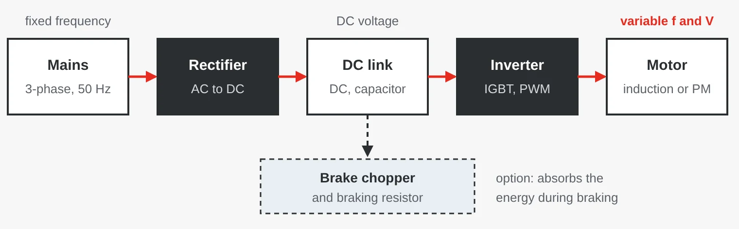
An induction motor on the mains runs at almost constant speed – a four-pole motor at 50 Hz at just under 1,500 rpm. A VFD rectifies the mains voltage into a DC voltage in the DC link. An inverter with IGBT transistors then creates a new three-phase voltage with any frequency and voltage. The motor speed is then fully adjustable, with soft starts and stops. The drive controls both induction motors and permanent magnet (PM) motors, which are more efficient but usually cannot run directly on the mains.
Why does speed control save energy?
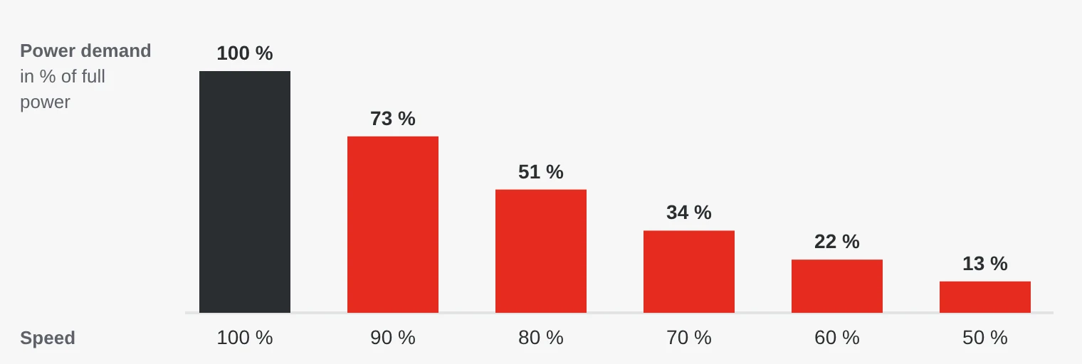
In centrifugal pumps and fans, the power demand rises roughly with the cube of the speed. At 80 per cent speed, the motor in theory needs only about half the power. With throttling, the motor runs at full speed and the energy is wasted in the valve or damper. Static head or back pressure reduces the saving, but it is often still large.
Where are VFDs used?
- Buildings – fans, circulation pumps and chillers in ventilation and heating.
- Water and wastewater – pumping stations and blowers in treatment plants. Soft starts and stops reduce water hammer.
- Factories and machine building – conveyors, mixers, extruders and compressors.
- Lifting – overhead cranes, gantry cranes and lifts, where the drive handles the brake sequence.
- Energy and marine – cooling water pumps in power plants and winches on ships.
V/f control or vector control?
| Control method | How it works | Suitable for |
|---|---|---|
| V/f control | Voltage follows frequency in a fixed ratio. | Pumps, fans and several motors on one drive. |
| Sensorless vector control | The drive calculates motor flux and torque from current and voltage. | Most machines. Good torque at low speed. |
| Closed-loop vector control | An encoder feeds back the actual speed. | Full torque at standstill, hoists and winders. |
PM motors generally need vector control. During commissioning, auto-tuning measures the motor data. Do not skip it.
Sizing – current, overload and duty
Start with the motor rated current. Two 15 kW motors can differ in current depending on pole count and efficiency.
Many drives have two ratings: normal duty (ND) for variable torque loads such as pumps and fans, and heavy duty (HD) for constant torque and heavy starts, as in conveyors and mixers. Typically, normal duty allows 110 % overload for 60 seconds and heavy duty 150 % for 60 seconds. Hoisting needs full torque at standstill, mechanical brake control and often an encoder.
Ratings apply at a given temperature, altitude and switching frequency. A hot cabinet, altitudes above 1,000 metres or a higher switching frequency often mean derating.
Braking and regeneration
When a motor brakes or lowers a load, it acts as a generator. Energy flows back into the DC link and the voltage rises until the drive trips on overvoltage.
- Braking resistor – a brake chopper switches in a resistor that turns the energy into heat. Simple and inexpensive. Smaller drives often have the brake chopper built in.
- Regenerative braking unit – returns the energy to the grid. Pays off with frequent braking in cranes, lifts and centrifuges.
- Active front end or matrix converter – the drive itself regenerates and draws a nearly sinusoidal current from the grid, with very low harmonics.
EMC, motor cable and bearing currents
Fast switching in the drive causes high-frequency interference, and the rectifier causes mains harmonics. The standard EN 61800-3 divides drive systems into categories:
| Category | Environment | Example |
|---|---|---|
| C1 | Residential and offices | Small drives in buildings, often with an extra filter. |
| C2 | As C1, installed by a professional | Buildings. Many drives have a built-in C2 filter. |
| C3 | Industrial | Factories with their own transformer. |
| C4 | Industrial, at least 1,000 V or 400 A | Large drive systems with an EMC plan. |
- Shielded motor cable – terminate the shield all the way round (360°) at both ends with EMC cable glands.
- Long cables – reflections can give voltage peaks of up to twice the DC link voltage at the motor. Above the maker’s limit, use a dV/dt or sine filter.
- RCDs – the EMC filter causes leakage current, and a fault can cause DC current to earth. Three-phase drives often need a type B RCD.
Bearing currents occur when the common mode voltage from the drive discharges through the motor bearings, etching flutes into the races. The bearing can then fail within months. The risk grows with motor size. Countermeasures are insulated bearings, a shaft grounding ring, common mode filters and correct shielding.
Communication, STO and mounting
Simple systems use digital inputs and a 0–10 V or 4–20 mA reference. Modern machines usually use a network: PROFINET in Siemens environments, EtherNet/IP with Rockwell, EtherCAT in machines with motion control and Modbus or BACnet in pumping stations and buildings. The control system can then also read current, torque, energy use and alarms.
STO (Safe Torque Off) removes motor torque through two independent channels. The function is defined in IEC 61800-5-2 and corresponds to stop category 0 in IEC 60204-1. With a safety card you can also get SS1, a controlled stop followed by STO. STO does not replace an isolator – the motor cable is still live.
Most drives are IP20 for cabinet mounting, where a few per cent of the power becomes heat to be removed. IP55 models are available for mounting out in the plant.
Common mistakes
- Choosing the drive by kW. A motor with many poles or low efficiency draws more current than a four-pole motor of the same power.
- A contactor breaks the motor circuit during operation. This can damage the drive output stage. Stop with STO or a stop command first.
- Forgetting the braking requirement. A large fan or a downhill conveyor can trip on overvoltage at every stop.
- Running the motor at low speed and high torque for long periods. A self-ventilated motor then overheats. Use a separate cooling fan or a larger motor.
Variable frequency drives from SCN
We offer drives from Yaskawa: general-purpose models from 0.1 kW, high-performance drives up to 630 kW and dedicated models for buildings, cranes and lifts, as well as regenerative braking units and the U1000 matrix converter. Tell us about the motor, load and environment, and we will help you choose size and options.
Examples from our range
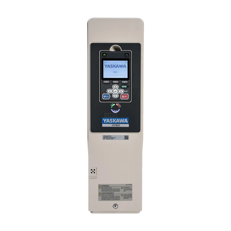 YaskawaHV600 HVAC InverterFor fans, pumps and compressors in buildings, with built-in C2 EMC filter, BACnet and Modbus RTU.View product →
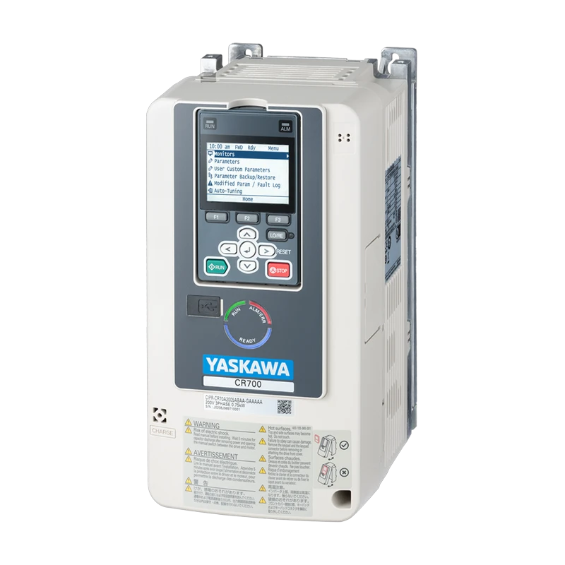 YaskawaCR700 Crane InverterCrane drive from 0.55 to 315 kW with a dedicated brake sequence and load check.View product →
 YaskawaU1000Matrix converter with ultra-low harmonics and full regeneration of braking energy.View product →
Erik Ahlqvist is Managing Director of SCN and has spent more than 20 years helping industrial companies choose the right electronics for demanding environments. He holds a BSc in Electronics from KTH Royal Institute of Technology, Stockholm.
LinkedIn profileFrequently asked questions
What is the difference between a VFD and a soft starter?
A soft starter only gives a smooth start, then the motor runs at full speed. A VFD controls the speed all the time and can therefore save energy.
Can I run a standard motor on a VFD?
Yes, most modern induction motors can. With long cables, a 690 V supply and large motors, check the motor insulation and protection against bearing currents.
What does STO mean on a VFD?
Safe Torque Off, a safety function that removes motor torque through two independent channels. It does not replace an isolator for electrical work.
Can a VFD run on single-phase power?
Yes, smaller drives take 230 V single-phase input and still supply three-phase to the motor, which is then usually connected in delta.
Unsure about size, braking or EMC filter? Ask us – you get an answer within 24 hours.
Ask us