




Condition monitoring with vibration sensors – getting started
A failing gearbox, pump or fan often shows up in its vibration weeks or months in advance. This guide covers what to measure, how ISO 20816 helps you judge the levels and how to get started – from the wind turbine to the pumping station.
 By Erik Ahlqvist, Managing Director of SCN · Updated 24 October 2026 · 7 min read
- Why – vibration reveals imbalance, misalignment and bearing damage long before a machine runs hot or gets noisy.
- What to measure – velocity in mm/s RMS for overall condition, acceleration and envelope for bearings and gears.
- Standards – the ISO 20816 series has replaced most of ISO 10816. Part 3 covers industrial machines above 15 kW, part 21 wind turbines.
- Wireless or wired – wireless for many machines and retrofits, wired for critical machines and continuous measurement.
- Getting started – start with the most critical machines, measure a baseline and set alarm limits from it.
Why condition monitoring?
Most machines are maintained either when they break or on a fixed schedule. The first means unplanned stops, the second replacing parts that would have lasted much longer. With condition-based maintenance you measure the machine’s condition and act when it is needed.
A bearing fault develops in stages. First come small, repeated impacts that only sensitive methods detect. Then vibration rises, followed by noise and finally temperature – often just before failure. The earlier you see the fault, the more time you have to plan the stop and order parts.
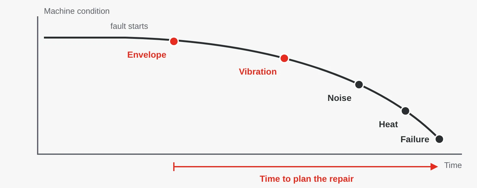
In a wind turbine, a main bearing or gearbox failure can require a large crane and weeks of downtime. In a pumping station or factory, a single pump, fan or conveyor can stop the entire flow.
What should you measure?
| Quantity | Unit | Shows |
|---|---|---|
| Velocity | mm/s RMS | Overall condition: imbalance, misalignment, looseness and soft foundations. Used in ISO 20816. |
| Acceleration | g or m/s² | High-frequency faults such as gear mesh problems in gearboxes. |
| Envelope | g | Repeated impacts from early bearing damage and poor lubrication. |
| Displacement | µm | Shaft movement in plain bearings and slow machines. |
| Temperature | °C | A late sign of friction and poor lubrication, but simple to measure. |
A frequency analysis (FFT) splits the signal into frequencies. A peak at running speed often points to imbalance, at twice running speed to misalignment and at the bearing fault frequencies to bearing damage. So you see not only that something is wrong, but also what.
Measure on the bearing housings, as close to the bearing as possible, radially and preferably axially too. A triaxial sensor measures all directions at once.
ISO 20816 – when is vibration too high?
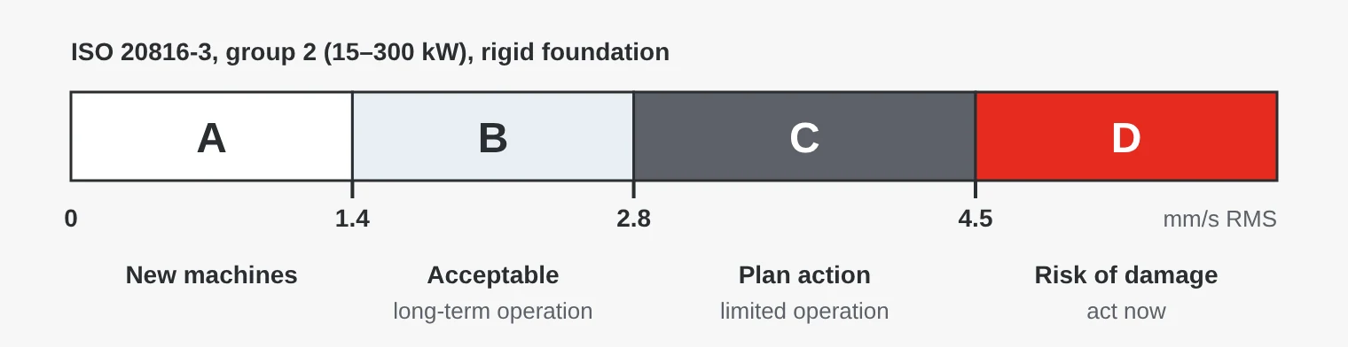
The ISO 20816 series replaces the older ISO 10816 and ISO 7919 and covers both bearing housing and shaft measurements. ISO 20816-3:2022 covers industrial machines above 15 kW running at 120 to 30,000 rpm and divides the level into four zones.
| Standard | Covers |
|---|---|
| ISO 20816-1 | General guidelines for measurement and evaluation |
| ISO 20816-3 | Industrial machines above 15 kW, such as motors, fans and compressors |
| ISO 20816-5 | Machine sets in hydropower and pumped storage plants |
| ISO 20816-21 | Horizontal axis wind turbines, replaces ISO 10816-21 |
| ISO 10816-7 | Centrifugal and other rotodynamic pumps. A new ISO 20816-7 is in preparation. |
The limits in the figure apply to machines of 15–300 kW on a rigid foundation, measured as velocity in mm/s RMS between 10 and 1,000 Hz. Larger machines and flexible foundations have higher limits.
The zones are a good start, but the most important signal is change. A machine that has always run at 1.5 mm/s and suddenly reads 2.5 mm/s has a problem, even if the level is still acceptable.
Wireless or wired sensors?
| Property | Wired | Wireless |
|---|---|---|
| Measurement | Continuous, catches fast events | Usually at intervals |
| Installation | Cable to every measuring point | Fast, good for retrofits and hard-to-reach places |
| Connection | 4–20 mA, Modbus RS485 or IO-Link to the PLC | Bluetooth, LoRaWAN or other radio via a gateway |
| Suits | Critical machines and protection functions | Many less critical machines on large sites |
Many sites combine both: wired sensors where a stop costs the most, wireless on the rest. Sensors with built-in FFT and alarms send only key values and alarms, so the control system is not flooded with raw data.
How to get started
- Choose machines. Assess what a stop costs, the lead time for spare parts and whether safety is affected. Start with the most critical.
- Choose measuring points. Bearing housings on the motor and driven machine. Velocity for overall condition, envelope for rolling bearings.
- Measure a baseline. Measure in normal operation, ideally at different loads and speeds, and record the operating state.
- Set alarm limits. Start from the ISO zones and adjust to the baseline. Use two levels: warning and alarm.
- Connect to existing systems. Send key values and alarms to the PLC, SCADA or maintenance system, where staff already look.
- Follow up. When an alarm has led to action, check what you found and adjust the limits.
- Loose or poorly mounted sensor. A magnetic base or thin sheet-metal cover damps high frequencies. Screw or bond the sensor to the bearing housing.
- Comparing different operating states. Vibration depends on speed and load. Compare at the same operating state, especially in wind turbines where speed follows the wind.
- Too many alarms. Limits that are too tight lead to alarms being ignored. Start cautiously and adjust over time.
- Temperature only. By the time a bearing runs hot, it is often too late to plan the stop.
Examples from different industries
- Wind power – main bearing, gearbox and generator. The main shaft turns slowly, so the sensor must handle low frequencies. Tower movement is measured with motion and inclination sensors.
- Hydropower – turbine and generator bearings, often complemented by sensors that measure shaft movement.
- Pumping stations – pumps and mixers at remote sites, where connected sensors save trips to the station.
- Factories – fans, compressors, conveyors and mills.
- District heating and CHP – circulation pumps, flue gas fans and fuel feed.
- Marine – engines, pumps and auxiliary machinery on board.
Condition monitoring sensors from SCN
We carry vibration sensors from KP Sensors with built-in frequency analysis and alarms, with Modbus or wireless connection, and sensors for temperature, humidity and inclination for the same environments. Tell us which machines you want to monitor and where the data should go, and we will help you get started.
Examples from our range
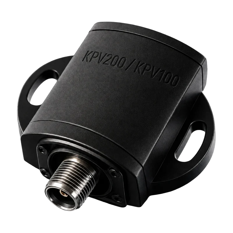 KP SensorsKPV200 Modbus Vibration SensorTriaxial vibration sensor with on-board FFT and alarms. Sends data over RS485 Modbus RTU straight to a PLC or monitoring system.View product →
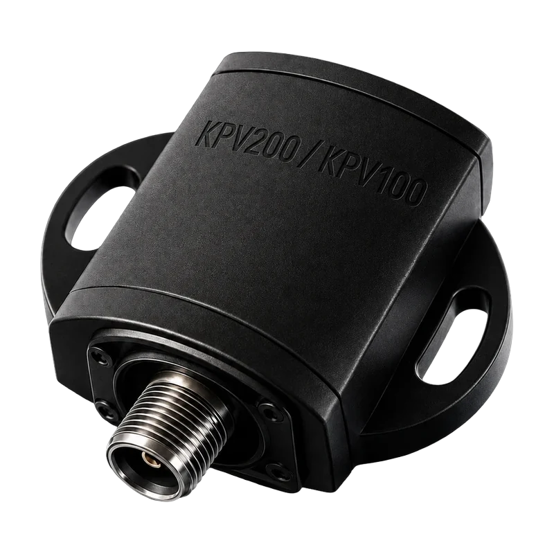 KP SensorsKPV100 Wireless Vibration SensorTriaxial sensor with Bluetooth and local alarm outputs, for motors, wind turbines and other machinery.View product →
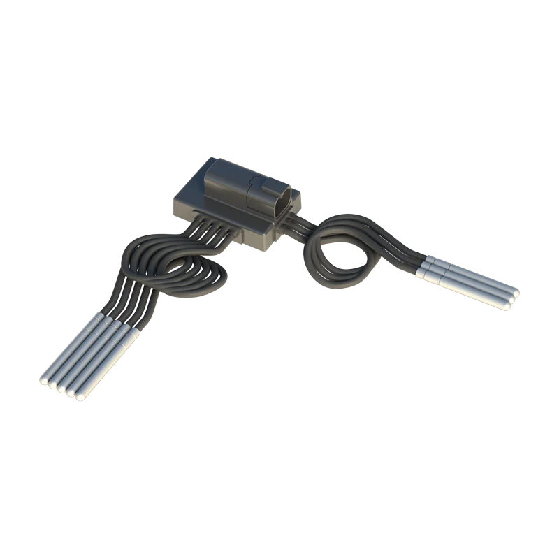 KP SensorsTempMux-8 Multipoint Temperature SensorReads up to eight PT1000 probes and reports over Modbus, for example to follow bearing temperatures.View product →
Erik Ahlqvist is Managing Director of SCN and has spent more than 20 years helping industrial companies choose the right electronics for demanding environments. He holds a BSc in Electronics from KTH Royal Institute of Technology, Stockholm.
LinkedIn profileFrequently asked questions
What is the difference between ISO 10816 and ISO 20816?
ISO 20816 is the newer series that replaces ISO 10816 and ISO 7919. ISO 20816-3:2022, for example, replaced ISO 10816-3:2009. Some older parts, such as ISO 10816-7 for pumps, still apply.
What vibration level is normal?
It depends on machine size and foundation. For machines of 15–300 kW on a rigid foundation, ISO 20816-3 puts the boundary between zones B and C at 2.8 mm/s RMS. The machine’s own baseline is often the best reference.
Can vibration sensors detect bearing damage?
Yes. Early damage shows best in envelope analysis, which picks up the repeated impacts as the rolling elements pass the defect. Later it also shows in vibration velocity and temperature.
How often should you measure?
Critical machines where faults can develop quickly should be monitored continuously. For other machines, measurements at regular intervals are enough, matched to how fast faults tend to develop.
What does RMS mean?
Root mean square, an effective value that reflects the energy of the vibration. Vibration velocity is usually given in mm/s RMS.
More guides
All guides →Want to start monitoring your machines? Ask us about sensors and connectivity – you get an answer within 24 hours.
Ask us